
14.1 Electrical Test
We perform the electrical test to check the functionality of the PCB. Using two-point measurements, we check all connections of the inner and outer layers for open and short circuits. We compare the measurements with the customer data (original netlist). The following serve as test points: SMD pads, test pads and plated through holes of any diameter.
Two different electrical test methods are available: fixture-based testing and flying probe testing. The appropriate method is selected based on the PCB design, batch size, and specific testing requirements.
In both cases, the following handling rule applies: For automated pick-up, the outline should be rectangular. However, this is necessary for your subsequent assembly process anyway!
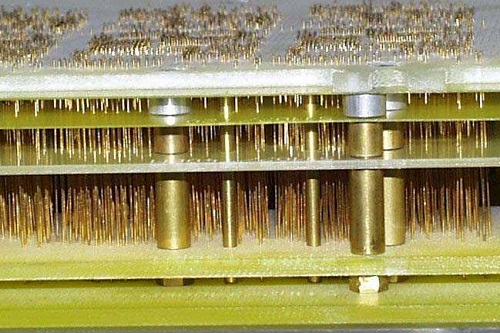
Fixture-Based Test System
Features & Advantages
- Short test time, as all test points are contacted simultaneously
- This makes it ideal for large, recurring series
Disadvantages
- A multi-layer test adapter has to be created (by drilling several test needle guide plates)
- Test area size is restricted (see table “Comparison of Test Methods”)
- Extremely fine grid structures: test needles can only be deflected to a limited extent
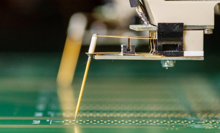
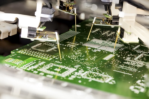
Flying Probe Test System
Features & Advantages
- Rapid test program creation (low initialization costs)
- Suitable for samples and small series (although this also depends on the number of test points)
- Unrestricted test area size (for max. production panel size, see table “Comparison of Test Methods”)
- Even the finest of component grids/pitch distances can be tested
Disadvantage
- Longer test time
| Fixture-Based Test System | Flying Probe Test System | |
|---|---|---|
| Max. test area size [mm] | 325 x 244 | 610 x 510 |
| Test voltage [V] | 35 - 250 | 10 - 1000 |
| Threshold for connection | 5 Ω - 1 kΩ | 1 Ω - 10 kΩ |
| Threshold for insulation | 100 kΩ - 100 MΩ | 100 kΩ - 100 GΩ |
Defective Piece in Sub-Panel/X-OUTs
Keywords
- Flying probe
- Electrical testing
- Bed-of-nails test
- X-outs
- Test and measurement methods