
3.8.1 Rigid-Flex PCB
Features & Advantages:
- Space and weight reduction
- Resulting assembly is more reliable thanks to the minimization of system interfaces (elimination of connectors and solder joints)
- Resulting stackup has better electrical and dielectric properties (impedance applications, shielding, defined losses)
- No extra electrical testing required for the individual components because there is only one assembly
- Cost savings in terms of the complete assembly (component placement, installation, repair)
- All materials that have been approved for a rigid-flex PCB can be found under 4.4 Base Materials | Rigid-Flex PCB
- The stackup conditions, tolerances, and requirements relating to the design, function, and reliability of rigid-flex PCBs are described in the following standards: IPC-6013, IPC-2223, IPC-4101
- Traces in the bending areas should be arranged perpendicular to the bending edge and should extend at least 1.0 mm into the rigid area
- No metallized holes and no components may be placed in the bending area
- Due to the increased moisture absorption by the flexible base materials used, all rigid-flex PCBs should be dried prior to component placement. Learn more under 3.8.7 Rigid-Flex PCB | Processing Recommendations
KSG manufactures rigid-flex PCBs for static applications only (max. bending cycles = 30 – 100, depending on technology).
UL approval has been granted for all material combinations (with adhesive-coated base material) (MOT = 105 °C/UL 94V-0).
If adhesive-free flex material is used, the following more stringent requirements can be met:
- Rigid-flex PCB for increased thermal stress – continuous operating temperatures of up to T = 130 °C
- Rigid-flex PCB for increased bending stress – number of bending cycles > 100 (with constant bending radii)
- UL approval with MOT (maximum operating temperature) = 130 °C
Our Technical Support Team and project engineers will be happy to discuss the material, layer buildup, and layout with you.
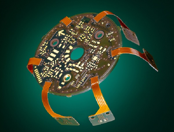
A rigid-flex PCB consists of both rigid and flexible areas. The rigid parts, which are often multi-layered, are joined together using a combination of flexible polyimide materials. The conductors are embedded within these materials. The polyimide materials offer maximum quality in the bending area and can handle the associated stress. By using the smallest possible bending radii, very small geometric shapes can be achieved.
One flex layer, asymmetric
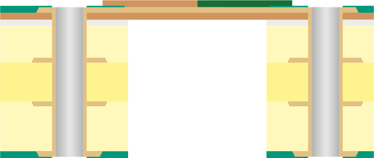
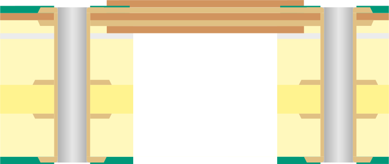
Two flex layers, asymmetric
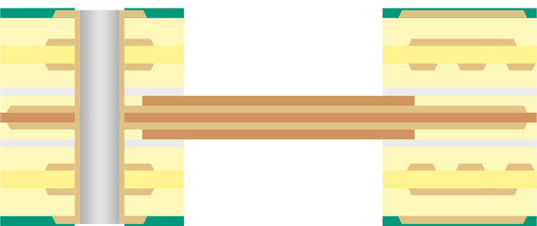
Two flex layers, symmetric

Technology Comparison – Typical Rigid-Flex Stackup Types
In this table, properties relating to the bending area such as bending radii, bending cycles, bending angles and other properties are evaluated in comparison of the three typical stackup types, one flex layer asymmetric, two flex layers asymmetric and two flex layers symmetric.
Frequently asked questions
How many bending cycles can rigid-flex PCBs withstand?
For rigid-flex PCBs, the number of bending cycles varies depending on the technology and should not exceed 30 to 100. For general design rules and specific bending properties (for comparison), see the section "Technology Comparison – Typical Rigid-Flex Stackup Types" under "3.8.1 Rigid-Flex | General". Guidelines for application and further details on bending radii and bending stress can be found under "3.8.7 Rigid-Flex | Processing Application Recommendations".
How do Semi-Flex and Rigid-Flex PCBs differ from each other?
Semiflex PCBs are an economical solution for applications requiring limited flexibility. They are made from a homogeneous FR4 composite and are flexibilized by specifically thinning certain areas through depth milling or by using a thin FR4 laminate. This construction is mainly suitable for one-time installation or a few bending cycles. On the other hand, Starrflex PCBs, due to their heterogeneous composition of FR4 material and a highly flexible polyimide laminate, are significantly more flexible in terms of bending radii and angles. Moreover, they are designed for applications requiring a higher number of bending cycles compared to Semiflex. However, Starrflex PCBs are also not suitable for applications where the flexible area/areas of the PCB are subjected to continuous mechanical movements. For more detailed information on the specifications and application areas of Semiflex and Starrflex technologies, we recommend first consulting the "General" sections of both PCB technologies.
Keywords
- Rigid-flex
- Bending radius
- Bending cycles
- Polyimide
- Coverlays
- Bending angles
- Design to Cost
- Multidimensional PCBs