
6.5 Markings | Other
Seriennummer
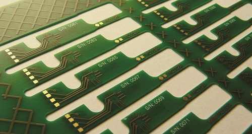
A serial number can be applied to each single PCB or each sub-panel (as an option, these numbers can run consecutively). The following points must be agreed:
- The start value for each production order or each production panel
- The number of digits (e.g., 2 digits)
- The content of the serial number per PCB, sub-panel, production panel, order
- How the numbers should be represented (e.g., plain text, data matrix code)
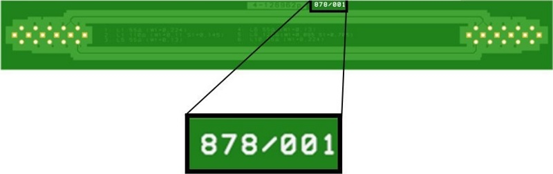
KSG-Internal Marking for Impedance Measurement Coupons
Each individual PCB or sub-panel is given a unique serial number (in the format: last 3 digits of the production order ID and 3-digit serial number)
Each individual PCB or sub-panel is given a unique serial number (in the format: last 3 digits of the production order ID and 3-digit serial number)
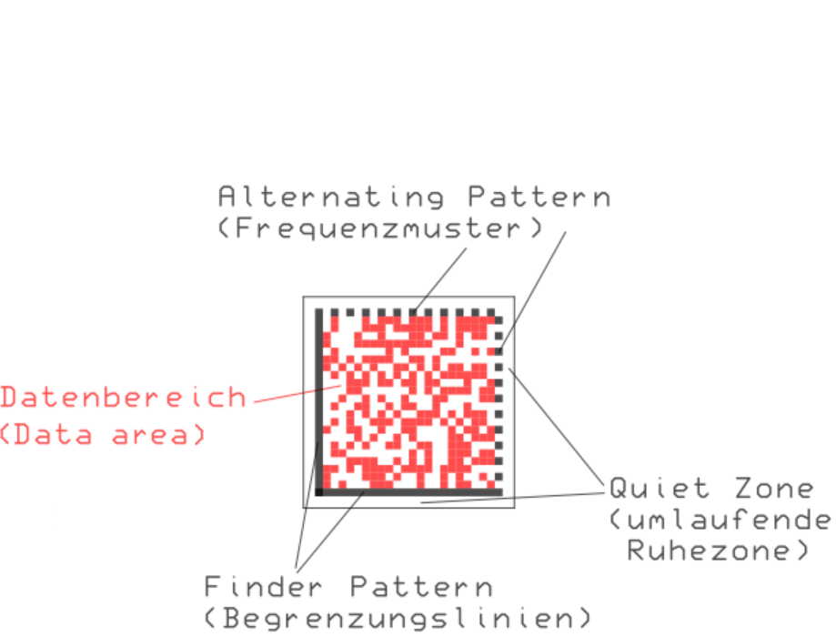
DMC = Data Matrix Code
Structure of the Code Image
The Two Pairs of Lines at the Edges (Solid Continuous Lines = Finder Pattern / Broken Lines = Timing Pattern)
The Two Pairs of Lines at the Edges (Solid Continuous Lines = Finder Pattern / Broken Lines = Timing Pattern)
- The solid lines (finder pattern) mark the boundary of the code. The finder pattern is used for orientation and to correct any distortion of the data matrix code, enabling it to be read from any angle.
- The Surrounding Quiet Zone
This empty zone runs all the way around the data matrix code. It does not contain any information or patterns. The quiet zone is at least one column or one row wide (preferably four times the width or height of a module) and is needed to separate the code from other optical image elements in the environment. - The Corner Opposite the Closed Edges
This corner allows the code schemas to be recognized quickly. Whenever the ECC 200 code schema is used with an even number of rows and columns, the element in the top right-hand corner is white. In the case of the other standardized code schemas with an odd number of rows and columns, the element in the top right-hand corner is always black. - The Data Area
This data area contains the actual binary information in coded form. Depending on the size of the matrix, this also defines how many pieces of information are possible.
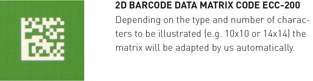
2D barcode in the form of an ECC 200 data matrix code
2D barcode in the form of a QR code
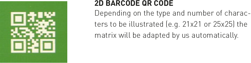
- Attention must be paid to the polarity of the barcode to be printed
- Barcodes are normally represented by black elements (bars, squares) on a white background = positive representation
- On a PCB, the light/dark contrast may look different -> if the code is applied using inkjet technology, white elements are printed on green mask -> this can lead to problems -> if necessary, switch the DMC representation to negative representation
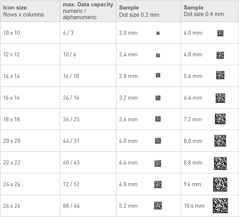
- The actual size depends on the number and type of coded elements (numeric = digits only; alphanumeric = digits, letters, special characters)

Further Marking Options
An extensive range of further marking options is available. These markings can be inserted according to customer requirements, such as:
An extensive range of further marking options is available. These markings can be inserted according to customer requirements, such as:
- Fire behavior according to railway standard EN 45545-2
- PCB no.
- PCB index
- Customer drawing number
- Drawing index
- Layout no.
- Revision status
- Position in sub-panel/in production panel
- E-test identifier
- ESD symbol
- ROHS logo
- Surface finish table/surface finish code
- IPC class
- Material identifier
- Country code
- And much more besides
Keywords
- Data Matrix code (DMC)
- Serial numbers
- QR codes
- Barcodes
- Markings