
17.6 Thermal Analyses
Reliable Prevention of Hot Spots
Temperature differences are a major risk factor for the service life of an electronic component. It’s therefore important to work out how to optimally distribute the heat on the PCB in a way that ensures thermal equilibrium.
We offer a two-stage service for thermal analyses: We provide software-based, thermographic simulations during the development and layout creation stages, as well as real load tests following the production of the initial prototypes. Both of these processes have the same goal: to detect and eliminate any hot spots and risk factors in the layout prior to series production.
We offer a two-stage service for thermal analyses: We provide software-based, thermographic simulations during the development and layout creation stages, as well as real load tests following the production of the initial prototypes. Both of these processes have the same goal: to detect and eliminate any hot spots and risk factors in the layout prior to series production.

Thermographic Simulation
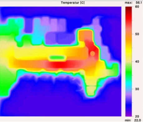
For the software-based, thermographic simulation, modeling is based on the layout data (e.g. from Gerber data) and other specifications. Additional information is also required, such as details of the layer stackup, base material, system structure, component characteristic values, current ratings, ambient conditions, and the installation situation. This is very important so that the subsequent operating conditions can be replicated as accurately as possible. Using the finite element method, the expected temperatures are calculated and thermographic images are clearly displayed.
Load Test in the Electrical Lab
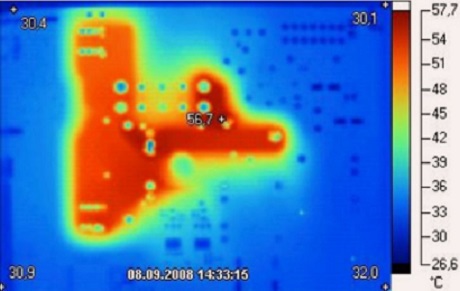
In the second stage, we test your PCB in the high-current laboratory under real conditions. Two high-current generators and a thermal imaging camera are used to apply the actual current levels to the high-current connections. After thermal equilibrium has been reached, the thermal imaging camera takes a surface measurement.
Keywords
- Thermography
- Thermal simulation
- Hotspots
- Thermal management
- Test and measurement methods
- Calculations and simulations