
12.1 Advanced Technology | Backdrilling
Back drilling (back hole drilling) is a special type of drilling technology.
It involves partially removing plated holes by means of deep drilling.
Depending on which PCB manufacturing technology is used, there are two types of “backdrilling” process:
It involves partially removing plated holes by means of deep drilling.
Depending on which PCB manufacturing technology is used, there are two types of “backdrilling” process:
- During the plating and conductive pattern creation processes, an additional depth-controlled drilling process is used to remove the non-functional part of the plated holes.
- During “milling”, the non-functional part of the plated holes is drilled away at the relevant depth.
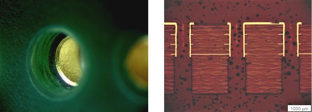
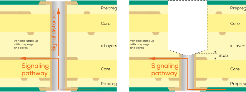
The stub describes the dimension of the remaining through-hole plating after the backdrilling process up to the first functional inner layer.
Backdrilling is particularly common in the case of high-frequency PCBs because it enables removal of the non-functional part of the plated hole that is responsible for distorting the signals.
The two images on the right show what happens to the signal both with and without backdrilling.
Backdrilling is particularly common in the case of high-frequency PCBs because it enables removal of the non-functional part of the plated hole that is responsible for distorting the signals.
The two images on the right show what happens to the signal both with and without backdrilling.
Frequently asked questions
What specific data is required for CAM preparation prior to backdrilling?
To enable CAM preparation for PCBs that involve backdrilling, a separate drill file is advisable. You can either use an individual drill file or you can use several if there are differences in the depth or side (top or bottom side) of the backdrilling holes. For optimum processing, we also recommend providing a detailed drawing as well. This should clearly identify the positions, sizes, and backdrilling depths of the backdrilling holes. Following this advice will make the CAM preparation process easier while minimizing the risk of errors.
Keywords
- Backdrilling
- Via stubs
- High frequency
- Vias